Scenario

Build the local event-detection layer

Central question

How does a physical tilt event become a digital signal, an audible alert, and a counted event in LabVIEW?

You are building a local IoT safety node that detects whether an object has been tilted or disturbed. Before this event can be logged or sent to the cloud, the system must reliably detect a digital input, trigger a local alert, and count each new event without counting the same tilt repeatedly.

This lab focuses on the local sensing and event-detection layer of an IoT system. It does not yet upload data to the cloud.

Physical tiltThe object changes orientation.
Switch stateThe ball switch opens or closes.
D2 HIGH/LOWArduino reads a digital state.
LabVIEW LINXLabVIEW receives the value.
Alert and countBuzzer command and event counter update.

LabVIEW does not directly sense tilt. It receives a digital HIGH or LOW value from Arduino and interprets that value based on the circuit logic.

Overview

Time, tools, and prerequisites

Pre-lab

20-30 minutes

Lab time

2.5-3 hours

Post-lab

30-45 minutes

Safety

Low-voltage digital electronics with buzzer noise awareness.

Software

LabVIEW, NI LabVIEW LINX Toolkit, and LINX firmware loaded to Arduino.

Hardware

Arduino Mega, tilt ball switch, 10 kΩ resistor, active buzzer, breadboard, jumper wires, and USB cable.

Prerequisite: LabVIEW LINX communication from previous labs.

Learning Outcomes

By the end of this lab, you should be able to...

Tilt switchExplain how the switch behaves electrically when orientation changes.
Defined logicExplain why pull-down resistors prevent floating digital inputs.
Digital statesDistinguish HIGH, LOW, open circuit, short circuit, and floating input.
Hardware buildBuild the tilt sensor on D2 and active buzzer on D3.
LINX I/OUse LabVIEW LINX Digital Read and Digital Write.
Logic inversionExplain why the Not function is required for the buzzer behavior.
Event countingUse shift registers to count new tilt events rather than loop iterations.
TroubleshootingDiagnose common wiring, LabVIEW, and logic faults.

Materials Checklist

Confirm the required materials

Gather the following software, hardware, and course resources before beginning the lab.

Pre-Lab

Predict before wiring

Activity A: Shift-register readiness

Activity B: Build the digital signal chain

Drag the events into order, or use the numbered selects if you prefer keyboard entry.

Activity C: Predict upright versus tilted readings

Hint after you predict

A floating input has no defined reference to decide HIGH or LOW. A pull-down resistor gives the input a defined LOW when the switch is open.

Activity D: Input or output?

ItemClassification
Tilt switch
Active buzzer
Arduino Digital Pin 2
Arduino Digital Pin 3
Round LED indicator
Waveform Chart

Checkpoint 1

Build the digital input and buzzer output circuit

Wire the tilt ball switch, 10 kΩ pull-down resistor, active buzzer, Arduino Mega, breadboard, and jumper wires. Use these pin assignments: Digital Pin 2 reads the tilt sensor and Digital Pin 3 drives the active buzzer.

Build focus

Use the instructor-provided schematic to place the tilt switch, pull-down resistor, active buzzer, Digital Pin 2, Digital Pin 3, 5 V, and GND.

Before powering, trace the current path for both the input circuit and the buzzer circuit.

Think it through

  • What does the tilt switch physically do when it changes orientation?
  • What makes the input HIGH?
  • What makes the input LOW?
  • Why does the circuit need a defined reference to ground?
  • What would happen if the pull-down resistor were removed?
  • Why does the active buzzer require correct polarity?
  • Is the buzzer sensing or acting?

Required evidence

Safe recovery sequence: disconnect USB power before moving wires. Verify the common ground, D2 pull-down connection, D3 buzzer connection and polarity, then confirm LINX firmware, serial port, and channel constants. Test one hypothesis at a time and limit prolonged buzzer exposure.

Checkpoint 2

Display tilt status in LabVIEW

Create a VI that opens a LINX connection, reads Digital Pin 2, displays the tilt state using a Round LED labelled Tilted, runs inside a while loop, waits 100 ms per loop, stops with a Stop button, and closes LINX after the loop ends.

A. Front Panel

Add a Round LED labelled Tilted and a Stop button.

B. Block Diagram

Arrange dataflow left to right: LINX Open, Digital Read, display logic, loop timing, Stop, LINX Close.

C. LINX Open

Keep LINX Open outside the loop so communication is not reopened every iteration.

D. Digital Read

Use LINX Digital Read with DI Channel constant set to 2.

E. While Loop

Put repeated sensor reading and display logic inside the loop.

F. Timing Delay

Use Wait Until Next ms Multiple with numeric constant 100.

G. Stop And Close

Use the Stop button for normal stopping and place LINX Close after the loop.

H. Run And Test

Verify the LED display for upright and tilted states.

Reason through the LED label.

If the raw input is HIGH when upright and LOW when tilted, should a front-panel indicator labelled Tilted display the raw signal or the inverted signal? Explain your choice.

Think it through

  • What does Digital Read return?
  • Does Digital Read measure voltage, resistance, or a logic state?
  • Why must the sensor be read repeatedly?
  • What is the purpose of the 100 ms wait?
  • What might happen if the loop runs as fast as possible?
  • Why should LINX Open stay outside the loop?
  • Why should LINX Close occur after the loop?

Evidence

Checkpoint 3

Turn tilt detection into an audible alert

Add LabVIEW control of the active buzzer using LINX Digital Write with DO Channel constant set to 3. Because the raw sensor reads HIGH when upright and LOW when tilted, the buzzer command should be the inverse of the raw tilt input.

Physical stateRaw Digital Pin 2 readingDesired buzzer stateDigital Pin 3 command
UprightHIGHOFFLOW
TiltedLOWONHIGH
Raw D2 value->Not function->D3 buzzer command->Active buzzer

Think it through

  • Why does the buzzer need the inverse of the raw sensor signal?
  • What would happen if the Not function were removed?
  • Is the Round LED showing raw sensor state or interpreted tilt state?
  • Should the LED and buzzer always agree?
  • What would happen if Digital Pin 2 and Digital Pin 3 were swapped?

Required evidence

The chooser records the selected filename as local evidence in this browser. It does not upload or submit your VI or report. Accepted formats are PNG, JPG, and PDF.

Checkpoint 4

Count events, not loop iterations

A loop running every 100 ms sees the same tilted state many times. If the program adds 1 every time it sees tilted, one physical tilt could be counted many times. To count events properly, compare current state with previous state and count only the desired transition.

Loop k-1: previous state->Loop k: current state->previous upright and current tilted?->count = count + 1

Required LabVIEW elements

  • Two shift registers
  • Numeric constant initialized to 0 for tilt count
  • False constant initialized for previous digital state
  • Not Equal? function
  • And function
  • Boolean To (1,0) function
  • Add function
  • Waveform Chart with digital display

What the Shift Registers store

Shift register 1: stores the current tilt count and carries it into the next loop iteration.

Shift register 2: stores the previous sensor reading so the current reading can be compared against it.

Think it through

  • Why is reading the current sensor value not enough to count tilts?
  • What is the difference between a state and an event?
  • What transition should count as a new tilt?
  • How does Not Equal? detect a change?
  • Why is the And function needed?
  • Why convert Boolean to 1 or 0?
  • What would happen if the sensor bounces between HIGH and LOW quickly?

Checkpoint 5

Visualize events over time

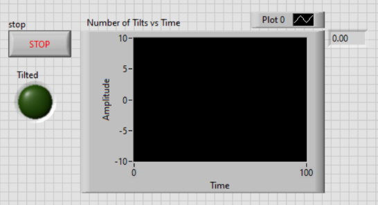
Add a Waveform Chart from Controls - Modern - Graph inside the while loop. Enable digital display, rename it Number of Tilts vs Time, change the Y-axis label to Number of Tilts, and wire it to the output of the Add function. Save the final VI as lab3_tilt_counter.vi.

Final front panel with Stop button, Tilted indicator, Number of Tilts vs Time chart, and count display.
The chart and numeric display show the tilt count over time.
TestExpected resultObserved result
Initial count0
After one tilt1
After three tilts3
Hold sensor tiltedNo repeated counting
Final front panel screenshotIncludedNo screenshot selected.
Final block diagram screenshotIncludedNo screenshot selected.

Think it through

  • Why should the graph increase in steps rather than continuously?
  • What would a flat line mean?
  • What would a rapidly increasing count while the sensor is held still mean?
  • How could switch bounce affect the chart?
  • Does the chart prove the physical sensor works, or only that the program count changes?

Checkpoint 6

Add a selectable buzzer mode

Add a toggle switch control that inverts active buzzer behaviour. Normal mode activates the buzzer when tilt is detected. Inverted mode activates the buzzer when there is no tilt.

ModeUprightTilted
Normal modeBuzzer OFFBuzzer ON
Inverted modeBuzzer ONBuzzer OFF

Implementation options

  • Add a Select function controlled by the toggle switch.
  • Add Boolean logic to choose between normal and inverted buzzer command.
  • Create a clearly labelled front-panel toggle.

Do not change the physical sensor reading. Change the buzzer command logic.

Required evidence

Think it through

  • What signal represents tilt detected?
  • What signal represents no tilt?
  • Should the toggle switch change the sensor reading or the buzzer command?
  • Where is the cleanest place to insert inversion logic?
  • What should happen if the toggle is changed while the VI is running?

Deliverables

Submission checklist

Reflection

Final questions

Learning Outcomes Achieved

What you can now demonstrate after completing this lab:

Tilt switchExplain how orientation changes the switch's electrical state.
Defined logicUse a pull-down resistor to prevent a floating input.
Digital statesDistinguish HIGH, LOW, open, shorted, and floating conditions.
Hardware buildBuild and verify the D2 tilt input and D3 buzzer output.
LINX I/OUse LabVIEW LINX Digital Read and Digital Write.
Logic inversionApply the Not function to obtain the intended alert behavior.
Event countingUse prior state to count transitions rather than loop iterations.
TroubleshootingIsolate wiring, communication, or logic faults with evidence.

Glossary

Key terms

Tilt ball switch
A switch whose open or closed state changes with orientation.
Active buzzer
A buzzer module that produces sound when powered with the correct polarity.
Digital input
A pin used to read a logic HIGH or LOW state.
Digital output
A pin used to command LOW or HIGH.
HIGH
A digital logic state interpreted as true or on.
LOW
A digital logic state interpreted as false or off.
Open circuit
A path that is not electrically connected.
Short circuit
A very low-resistance connection between two points.
Floating input
An input with no defined HIGH or LOW reference.
Pull-down resistor
A resistor that defines an input as LOW when the switch is open.
Arduino Digital Pin
A microcontroller pin that can read or write digital logic.
LabVIEW
A graphical programming environment.
VI
Virtual Instrument, a LabVIEW program.
Front Panel
The user-facing controls and indicators of a VI.
Block Diagram
The graphical program logic of a VI.
LINX
LabVIEW toolkit for communicating with supported hardware such as Arduino.
Digital Read
A LINX block that reads a digital input channel.
Digital Write
A LINX block that writes a digital output command.
While Loop
A repeated LabVIEW structure that continues until a stop condition is met.
Wait Until Next ms Multiple
A timing function used to pace loop execution.
Stop button
A controlled way to end a VI and allow cleanup logic to run.
Abort button
An emergency interruption that should not be normal operation.
Shift register
A loop feature that carries a value from one iteration to the next.
Previous state
The sensor value remembered from the prior loop iteration.
Current state
The sensor value read during the current loop iteration.
Event
A change or transition that happens at a moment in time.
State
A condition that may remain true for many loop iterations.
Transition
A change from one state to another.
Boolean
A true/false value.
Not function
A Boolean function that inverts true to false or false to true.
And function
A Boolean function that is true only when required inputs are true.
Not Equal?
A comparison function that detects when two values differ.
Boolean To (1,0)
A conversion that turns true into 1 and false into 0.
Waveform Chart
A LabVIEW indicator that displays values over time.
Switch bounce
Rapid electrical changes when a mechanical switch changes state.
IoT event node
A local device that detects and counts events before later network or cloud connection.