Scenario

Build the local force-measurement layer

Central question

How does an applied force become a measurable voltage and then a live LabVIEW reading?

You are building a local IoT measurement node that can detect applied force. Before this measurement can be logged or sent to the cloud, the system must safely excite a load cell, amplify its very small voltage output, read the amplified voltage with Arduino, and display a trustworthy live value in LabVIEW.

This lab focuses on the local sensing and signal-conditioning layer. It does not yet upload force data to the cloud.

Applied forceMetal bar bends slightly.
Strain gaugesResistance changes in the bridge.
SIG+ and SIG-Tiny differential voltage appears.
AmplifiersV2 and then V3 increase the signal.
A0 and LabVIEWVoltage is displayed live.

LabVIEW does not directly measure force. It reads amplified voltage. Calibration is required to display force units.

Overview

Time, tools, and prerequisites

Pre-lab

30-45 minutes

Lab time

3 hours

Post-lab

45-60 minutes

Safety

Low-voltage electronics with mechanical-force and op-amp wiring caution.

Software

LabVIEW, NI LabVIEW LINX Toolkit, and LINX firmware loaded to Arduino.

Hardware

Arduino Mega, breadboard, jumper wires, load cell, screw terminals, LMC6484 op-amp, 10 kΩ, 100 kΩ, and 1 MΩ resistors, voltmeter, and USB cable.

Prerequisite: LabVIEW LINX analog reading from previous labs.

Learning Outcomes

By the end of this lab, you should be able to...

Load-cell behaviorExplain how applied force causes strain in a load cell.
Strain gaugesExplain how deformation becomes resistance change.
Bridge outputExplain why the Wheatstone Bridge produces a small differential voltage.
MeasurementMeasure SIG+ to SIG- and compare readings across load conditions.
AmplificationBuild and test the first and second op-amp stages.
Gain mathCalculate first-stage, second-stage, and total cascaded gain.
LabVIEW readoutRead amplified voltage using Arduino A0 and LabVIEW LINX.
Design revisionPropose a modification that halves total amplification.

Materials Checklist

Confirm the required materials

Gather the following software, hardware, and measurement tools before beginning the lab.

Pre-Lab

Predict before building

Activity A: Arrange the measurement chain

Drag the events into order, or use the numbered selects if you prefer keyboard entry.

Hint after you predict

Arduino's analog input has limited resolution. Amplifying a tiny sensor voltage allows more of the input range to be used, improving useful measurement sensitivity.

Activity B: Gain calculations

CalculationGiven valuesYour answerCheck
AV1 = R3 / R1R3 = 1 MΩ, R1 = 10 kΩ
AV2 = 1 + R6 / R5R6 = 100 kΩ, R5 = 10 kΩ
AVtotal = AV1 * AV2100 * 11

Checkpoint 1

Build the raw load-cell sensing circuit

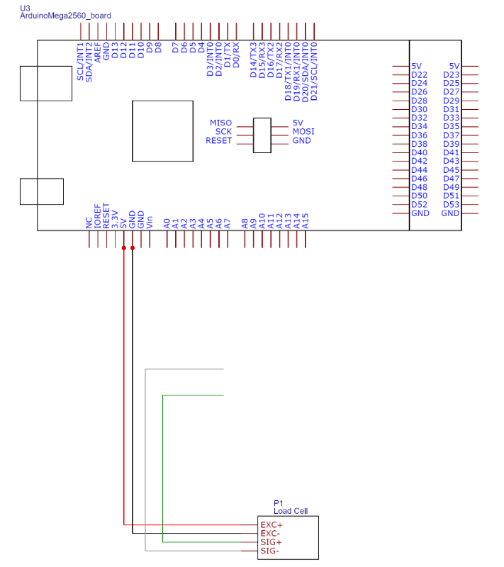
Use Arduino 5 V and GND, connect the load cell through screw terminals, and construct the initial circuit at the far end of the breadboard because later amplifier stages will be added.

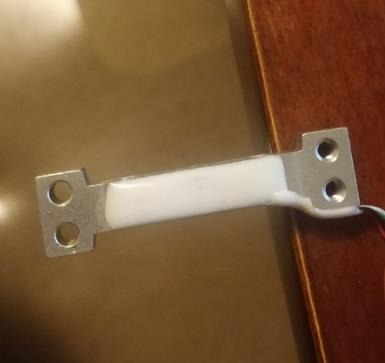
Load cell mounted at the edge of a table.
Pin one end of the load cell and apply force gently in the indicated direction.
Initial load-cell circuit connected to Arduino 5 volts and ground.
Arduino 5 V and GND excite the load-cell bridge before amplification.
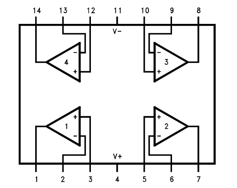
LMC6484 op-amp pinout diagram showing four op-amps and pin numbers.
Use the LMC6484 pin reference before wiring the amplifier stages.

Think it through

  • Which wires supply the load cell?
  • Which wires carry the measurement signal?
  • Why are SIG+ and SIG- measured relative to each other first?
  • What would happen if SIG+ or SIG- were loose?
  • Why is the load cell placed at the edge of the table?
  • Why must force be applied in the indicated direction?

Required evidence

Checkpoint 2

Measure the tiny differential output

Put the load cell at the edge of the table, pin one end carefully, and apply force gently to the other end in the indicated direction. Record a range rather than trusting one reading.

ConditionMeasurement pointVoltageNotes
No loadSIG+ to SIG-
Gentle loadSIG+ to SIG-
Maximum safe loadSIG+ to SIG-

Think it through

  • Is the raw signal single-ended or differential?
  • Is the no-load output exactly zero? Why or why not?
  • What might cause the reading to drift?
  • Why might hand-applied force produce inconsistent readings?
  • Why is this raw signal not yet ideal for direct IoT measurement?

Checkpoint 3

Amplify the load-cell signal with the first op-amp stage

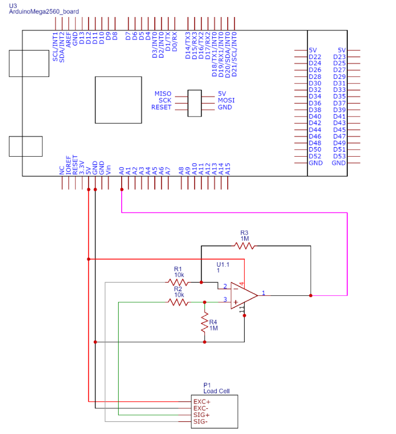
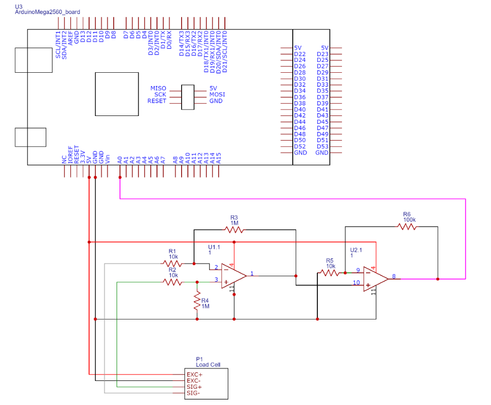
Add the first-stage amplifier using the LMC6484. Use pin 2 for SIG-, pin 3 for SIG+, and pin 1 for output V2. Use R3 = R4 = 1 MΩ and R1 = R2 = 10 kΩ. The ideal gain is AV = R3 / R1 = 100.

First LMC6484 amplifier stage for the load-cell signal.
In the first-stage amplifier, R3/R1 sets the ideal gain of 100 for the V2 output.
Before connecting V2 to Arduino A0, verify that V2 remains within the Arduino analog input range.

Safe recovery sequence

Disconnect power before changing the circuit. Confirm the LMC6484 orientation and pin numbers, common ground, feedback path, and 10 kΩ/100 kΩ/1 MΩ resistor identities. Measure the output before reconnecting A0, and change one suspected fault at a time.

ConditionMeasurement pointExpected relationshipVoltageNotes
No loadV2 to GNDAmplified output
Gentle loadV2 to GNDLarger or smaller depending on force direction
Maximum safe loadV2 to GNDWithin Arduino input range

Think it through

  • Why do we amplify the load-cell signal?
  • What does the resistor ratio determine?
  • Why are R3 and R4 equal?
  • Why are R1 and R2 equal?
  • What does V2 represent?
  • What would happen if SIG+ and SIG- were reversed?
  • How can you verify that the gain is approximately correct?

Checkpoint 4

Add a non-inverting second-stage amplifier

Add the second-stage amplifier using op-amp number three on the LMC6484 chip, pins 8, 9, and 10. Use R5 = 10 kΩ and R6 = 100 kΩ. The additional ideal gain is AV = 1 + R6 / R5 = 11.

Complete two-stage LMC6484 amplifier circuit connected to Arduino analog input.
The non-inverting second stage increases V2 to V3 before Arduino A0 reads it.

V3 should be about 11 times greater than V2, subject to supply and saturation limits. Verify V3 is safe before connecting it to Arduino A0.

ConditionV2 measuredV3 measuredV3/V2 ratioNotes
No load
Gentle load
Maximum safe load

Think it through

  • Why add a second stage instead of changing the first stage?
  • What does non-inverting mean?
  • Why is the gain 1 + R6/R5 rather than R6/R5?
  • What is the ideal total gain of the two stages?
  • What is op-amp saturation?
  • How could excessive gain make the measurement worse?

Checkpoint 5

Display amplified voltage in LabVIEW

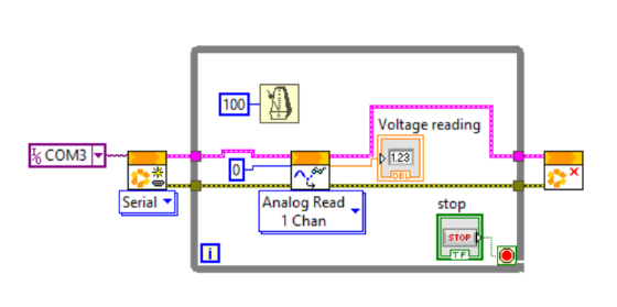
Create a LabVIEW VI that reads the amplified signal on Arduino A0 and displays it with a numeric indicator named Voltage Reading.

LabVIEW block diagram showing LINX Open, Analog Read channel 0, timing, stop control, and voltage reading indicator.
Read Arduino analog channel 0 and display the amplified voltage.
V3->Arduino A0->LINX Analog Read->LabVIEW Voltage Reading
A. Front Panel

Add a numeric indicator named Voltage Reading.

B. Block Diagram

Use LINX Open, LINX Analog Read, While Loop, Wait Until Next ms Multiple, Stop button, and LINX Close.

C. Analog Read

Set Analog Channel constant to 0.

D. Timing

Set Wait Until Next ms Multiple to numeric constant 100.

E. Stop And Close

Use Stop for normal shutdown and keep LINX Close after the loop.

F. Run And Compare

Repeat force application and compare LabVIEW displayed range with voltmeter V3 range.

Required evidence

Think it through

  • What physical quantity does Arduino A0 actually measure?
  • Does LabVIEW display force or voltage in this lab?
  • Why should LabVIEW match the voltmeter range?
  • Why is the while loop needed?
  • Why use a 100 ms wait?
  • What is required to display force rather than voltage?

The chooser records the selected filename as local evidence in this browser. It does not upload or submit your VI or report. Accepted formats are PNG, JPG, and PDF.

Checkpoint 6

Redesign the circuit to halve total amplification

The original ideal gains are AV1 = 100, AV2 = 11, and AVtotal = 1100. The halved ideal total gain is 550. Do not change the circuit while powered. Confirm modified resistor values and expected output range before reconnecting Arduino A0.

Valid design paths

  • Reduce first-stage gain while keeping the second stage unchanged.
  • Reduce second-stage gain while keeping the first stage unchanged.
  • Use available course components if possible.
  • Propose theoretical resistor values if the exact resistor is not physically available.

Required evidence

Think it through

  • Which stage is easier and safer to modify?
  • If you halve one stage's gain, what happens to total gain?
  • Are the required resistor values available in the lab kit?
  • Would the new output still use enough of the Arduino input range?
  • Would the new output avoid saturation?
  • What measurement would show that your redesign worked?

Deliverables

Submission checklist

Reflection

Final questions

Learning Outcomes Achieved

What you can now demonstrate after completing this lab:

Load-cell behaviorExplain how applied force produces strain.
Strain gaugesTrace deformation to a resistance change.
Bridge outputExplain the load cell's small differential voltage.
MeasurementMeasure SIG+ to SIG- across controlled load conditions.
AmplificationBuild and verify both LMC6484 amplifier stages.
Gain mathCalculate and compare first-stage, second-stage, and total gain.
LabVIEW readoutRead the safe amplified voltage through Arduino A0 and LINX.
Design revisionPropose and justify a circuit revision that halves total gain.

Glossary

Key terms

Load cell
A sensor assembly that converts applied force into an electrical signal.
Strain gauge
A resistive element whose resistance changes when stretched or compressed.
Force
A push or pull applied to the load cell.
Strain
Small deformation caused by applied force.
Wheatstone Bridge
A resistor bridge used to convert small resistance changes into a differential voltage.
Excitation voltage
The supply voltage used to power the sensor bridge.
SIG+
Positive side of the differential load-cell signal.
SIG-
Negative side of the differential load-cell signal.
Differential voltage
Voltage measured between two signal nodes.
Single-ended voltage
Voltage measured relative to a common ground reference.
Ground reference
The 0 V reference used by the circuit and measurements.
Op-amp
Operational amplifier used here to amplify sensor voltage.
LMC6484
The op-amp component used in the lab procedure and materials list.
Gain
The ratio between output signal size and input signal size.
First-stage amplifier
The differential amplifier producing V2.
Second-stage amplifier
The non-inverting amplifier producing V3.
Non-inverting amplifier
An amplifier whose output has the same polarity trend as its input.
Feedback resistor
A resistor connected in the amplifier feedback path that helps set gain.
Source resistor
A resistor in the gain-setting network.
Saturation
When the op-amp output cannot increase further because it reaches supply limits.
Arduino Analog Pin
A microcontroller input that measures voltage.
A0
Arduino Analog Pin 0.
ADC
Analog-to-digital converter.
LabVIEW
A graphical programming environment.
VI
Virtual Instrument, a LabVIEW program.
Front Panel
The user-facing controls and indicators of a VI.
Block Diagram
The graphical program logic of a VI.
LINX
LabVIEW toolkit for communicating with Arduino.
Analog Read
A LINX block that reads an analog voltage channel.
While Loop
A repeated LabVIEW structure.
Wait Until Next ms Multiple
Timing function used to pace loop execution.
Stop button
A controlled way to end a VI and allow cleanup logic to run.
Abort button
An emergency interruption that should not be normal operation.
Voltage Reading
The LabVIEW numeric indicator for the amplified voltage.
Calibration
Relating voltage output to known force or weight values.
Sensor offset
Nonzero output when no load is applied.
Noise
Small unwanted variation in measured signal.
IoT sensing node
A local device that senses and conditions data before later cloud connection.