Prepare

Lab scenario and setup

You are building a local IoT motion-control node. The system must accept either a physical input from a potentiometer or an HMI command from LabVIEW, convert that command into a safe servo pulse width, and move a servo motor predictably. In automatic mode, the system performs a repeated waving motion based on speed and number of waves.

This lab focuses on the local motion-control and HMI layer of an IoT system. It does not yet upload motion data or commands to the cloud.

Software

LabVIEW, NI LabVIEW LINX Toolkit, and LINX firmware loaded to Arduino.

Hardware

Arduino Mega, USB cable, breadboard, servo motor, potentiometer, 8 jumper wires, and the servo motor plastic arm attachment.

Required pins

Analog Pin 0 for potentiometer input. Digital Pin 7 for the servo signal.

Learning outcomes

Servo wiringIdentify servo power, ground, and signal wires.
Safe circuit buildWire a servo motor and potentiometer to Arduino Mega safely.
Analog inputRead potentiometer voltage from A0 using LINX.
ScalingScale voltage to angle, then angle to servo pulse width.
LINX servo controlUse Servo Open, Servo Write, Servo Close, and LINX Close.
HMI modesBuild Manual and Automatic LabVIEW front panels.
Automatic logicUse Case Structures, Formula Nodes, SubVIs, local variables, and previous-state values.
TroubleshootingDiagnose wiring, scaling, servo-range, and LabVIEW logic faults.

Materials Checklist

Confirm the required materials

Gather the following software, hardware, and course resources before beginning the lab.

A. Build the command chain

Drag the events into order, or use the numbered selects if you prefer keyboard entry.

Choose an order for every event.

B. Predict scaling values

PromptExpected relationshipYour answerCheck
Angle at V = 0 VAngle = V / 5 * 180
Angle at V = 2.5 VAngle = V / 5 * 180
Angle at V = 5 VAngle = V / 5 * 180
Pulse width at 0 degreesLRV = 600, URV = 2400
Pulse width at 90 degreesLRV = 600, URV = 2400
Pulse width at 180 degreesLRV = 600, URV = 2400

Checkpoint 1

Build the physical command-and-motion circuit

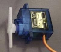
Photo of a servo motor with the plastic arm attachment fitted to the shaft.
Attach the servo motor plastic arm attachment before testing servo motion.
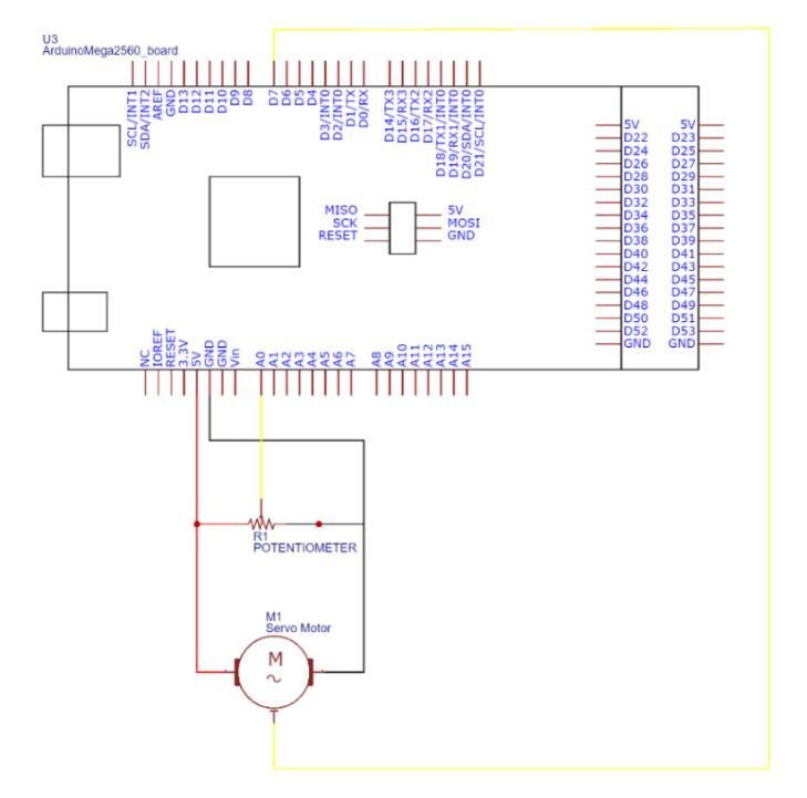
Schematic showing Arduino Mega connected to a potentiometer and servo motor.
Connect the potentiometer to A0 and the servo signal to Digital Pin 7.
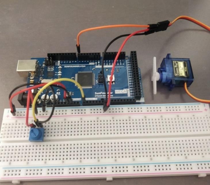
Breadboard photo showing the Arduino Mega, potentiometer, and servo motor wiring.
Compare your wiring with this Arduino, breadboard, potentiometer, and servo layout.

Breadboard rails

  1. Positive row to Arduino 5 V.
  2. Negative row to Arduino GND.

Servo motor

  1. Brown GND wire to negative rail.
  2. Red VCC wire to positive rail.
  3. Orange PWM wire to Arduino Digital Pin 7.

Potentiometer

  1. One outside terminal to negative rail.
  2. Other outside terminal to positive rail.
  3. Middle terminal to Arduino Analog Pin 0.

Record the potentiometer voltage range

After the circuit passes its wiring checks, use a multimeter to measure between the potentiometer middle terminal (the A0 output) and GND. Turn only the potentiometer knob while measuring; do not move wires while the circuit is powered. These values establish the physical voltage range that later becomes the Manual angle command.

Potentiometer positionMultimeter measurement pointMeasured output voltage
Fully turned leftMiddle terminal / A0 to GND V
Middle positionMiddle terminal / A0 to GND V
Fully turned rightMiddle terminal / A0 to GND V
Think it through
  • Which component is the input device?
  • Which component is the output device?
  • What does the potentiometer physically change?
  • What does Arduino A0 measure?
  • What does the servo signal wire receive?
  • Why must the servo and Arduino share ground?
  • What would happen if the red and brown servo wires were reversed?
  • What evidence would show the circuit is safe to power?

If a wiring check fails: disconnect power before correcting it, then recheck servo polarity, D7, A0, common ground, the arm attachment, and clearance around the moving shaft before powering again.

Checkpoint 2

Open Arduino, read voltage, and command the servo

Build the main VI that communicates with Arduino and the servo. Begin with a basic fixed pulse-width test before scaling.

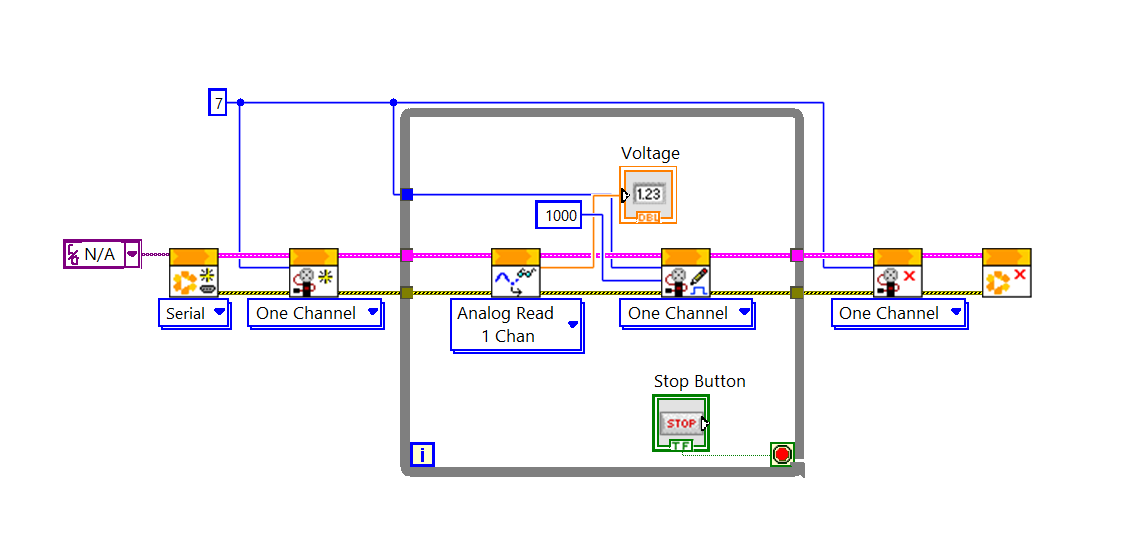
LabVIEW block diagram opening LINX and the servo channel, reading analog voltage inside a While Loop, writing a fixed pulse width, and closing both resources.
Wire LINX Open, Servo Open, Analog Read, Set Pulse Width, Servo Close, and LINX Close in sequence.
A. LINX Open
Add LINX Open, create the Serial Port constant, and set it to COM3 or the correct Arduino COM port.
B. Servo Open
Add LINX Servo Open and set Servo Channel to 7.
C. While Loop
Place the loop, wire LINX resource and error tunnels, and create a Stop control.
D. Analog Read
Add LINX Analog Read inside the loop and set Analog Channel to 0. Create a Voltage indicator.
E. Set Pulse Width
Add Servo Write / Set Pulse Width inside the loop, set Servo Channel to 7, and initially use 1000 microseconds.
F. Close functions
Add Servo Close after the loop, then LINX Close. Wire resource and error lines through all blocks.
Find the safe pulse-width limits: use the Manual control to increase or decrease the pulse width cautiously. Identify the lowest value that places the servo at approximately 0 degrees and the highest value that places it at approximately 180 degrees. Stop before the servo strains against its mechanical end stop, and record the two limits in the table in the next stage.
If the fixed pulse-width test does not move safely
Stop the VI normally and disconnect power if the servo is blocked, hot, or driving against an end stop. Verify the LINX firmware and COM port, Servo Channel 7, Analog Channel 0, common ground, and wiring before changing one item and retesting.
Think it through
  • Why does the servo need to be opened before writing commands?
  • What does Analog Read return?
  • Does Analog Read measure angle directly?
  • What does Set Pulse Width send to the servo?
  • Why should Servo Close and LINX Close occur after the loop?
  • What could happen if the VI is aborted before close functions run?
  • What does a constant pulse width of 1000 microseconds test?
Target servo angleYour pulse-width value (microseconds)Observed response / notes
0 degrees
90 degrees
180 degrees

Use the lower and upper limits you found above, then test intermediate values to map the pulse width that produces 0, 90, and 180 degrees. These measurements become the calibration points for the angle-to-pulse-width conversion.

Checkpoint 3 and 4

Build the Manual/Automatic front panel and scale voltage to angle

Add the front-panel HMI controls, then create the Manual case that turns potentiometer voltage into an angle command. For this first introduction to the structures, review the Case Structure skill and Formula Node skill in the course skill tree.

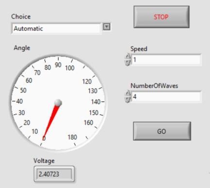
LabVIEW front panel with Choice Enum, Angle gauge, Speed and NumberOfWaves controls, GO button, Stop button, and Voltage indicator.
Use this front panel as the visual reference for the Manual/Automatic HMI controls.

Enum

Name it Choice. Right-click the Enum control, choose Properties, open Edit Items, select Insert, and add Manual and Automatic as the two items.

Gauge

Find it in Controls > Modern > Numeric > Gauge. Name it Angle, then right-click the gauge, choose Properties, open the Scale tab, and set the scale range to 0–180 degrees.

Controls

Add Speed and NumberOfWaves as Numeric controls. Add GO as an OK button, and keep the Voltage indicator.

How the Manual case fits into the Case Structure

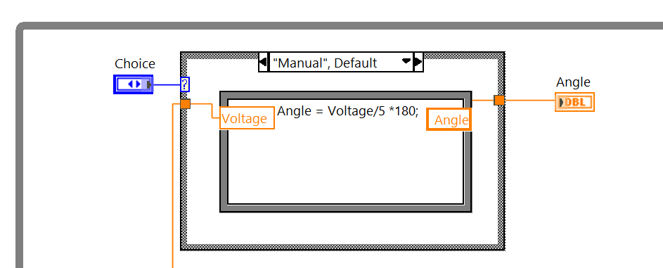
LabVIEW Manual Case Structure selected by the Choice Enum, converting Voltage to Angle and sending the result to the Angle indicator
This Case Structure view shows the Choice selector, the active Manual case, the voltage input, and the Angle output tunnel.

The Case Structure chooses which command path is active. Wire the Choice Enum to the selector terminal on the left side of the Case Structure; when the user selects Manual, LabVIEW displays and executes the Manual case, while Automatic will select the separate automatic-wave case later.

Inputs

The Manual case receives the potentiometer voltage from Analog Read. The Choice Enum is the selector input that determines which case is shown and executed.

Processing

Inside the Manual case, the Formula Node maps the 0-5 V input to a 0-180 degree command using Angle = V / 5 * 180;.

Output

Wire the Formula Node's Angle output to the Angle indicator and through the Case Structure output tunnel. This single angle output will then continue, on the next stage of this lab, to the shared pulse-width scaling and servo command.

Build sequence: create the Manual and Automatic Enum items, wire Choice to the Case Structure selector, place the Formula Node in the Manual case, connect the voltage input and Angle output, then confirm that the Manual case produces one clean angle value for the next stage.

Think it through
  • What is the input to the Manual case?
  • What is the output of the Manual case?
  • Why divide by 5?
  • Why multiply by 180?
  • What happens if the potentiometer does not reach exactly 0 V or 5 V?
  • Is the Angle gauge a measured shaft angle or a commanded angle?
  • What would happen if the two outside potentiometer terminals were swapped?

Checkpoint 5

Convert angle into servo pulse width

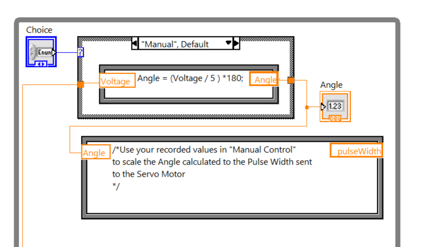
Place a Formula Node below the Case Structure so the Manual and Automatic cases share one angle-to-pulse-width conversion. The Case Structure should produce one numeric Angle value; the Formula Node should receive that value, apply the calibrated lower and upper pulse limits, and produce one numeric PW output for Set Pulse Width.

The mapping should preserve the endpoints: 0 degrees corresponds to your measured lower limit, 180 degrees corresponds to your measured upper limit, and intermediate angles scale proportionally between them. Use input and output terminals on the Formula Node border with names that match the block-diagram wiring.

LabVIEW Case Structure and Formula Node showing Choice selecting Manual, Voltage converted to Angle, and Angle passed toward pulse-width scaling.
Use this as a wiring and architecture reference: the Choice Enum selects the Manual case, the voltage is converted to an Angle, and that angle is passed to the shared pulse-width conversion. Recreate the structure with your own calibrated limits from Manual Control.

Add input Angle. Add output PW. Connect PW to the Pulse Width input of Set Pulse Width One Channel.

Use your recorded potentiometer range: revisit the fully-left, middle, and fully-right voltages from Build Circuit. They are a physical reference for how the knob changes the Manual angle command. The direction may be reversed depending on which outside potentiometer terminal is connected to 5 V, but the Formula Node at this stage receives the resulting Angle, not the raw voltage. Use the three recorded positions to reason about the expected low, middle, and high pulse-width commands before testing.
Temporary Manual-case test: LabVIEW may show an error because the Automatic case does not yet have its input mapped. To test the Manual case only, temporarily wire the Voltage input directly to the Angle output in the Automatic case so the Case Structure is complete. This is only a temporary test connection; it is not the final Automatic-case implementation.
AngleYour measured or adjusted valueNotes
0 degrees
90 degrees
180 degrees
Think it through
  • Why does the servo need pulse width rather than only an angle number?
  • What does 1500 microseconds usually represent?
  • Why might a different servo require different limits?
  • What could happen if the pulse-width range is too wide?
  • How could you test safe limits cautiously?
  • What is the difference between commanded angle and actual servo position?
  • Why should pulse width be bounded?

Checkpoint 6

Create a reusable automatic-wave SubVI

Create a new Blank VI for automatic waving. Add front-panel controls and indicators, then create a Formula Node using the current NI documentation. Build and explain your own logic rather than copying a finished program.

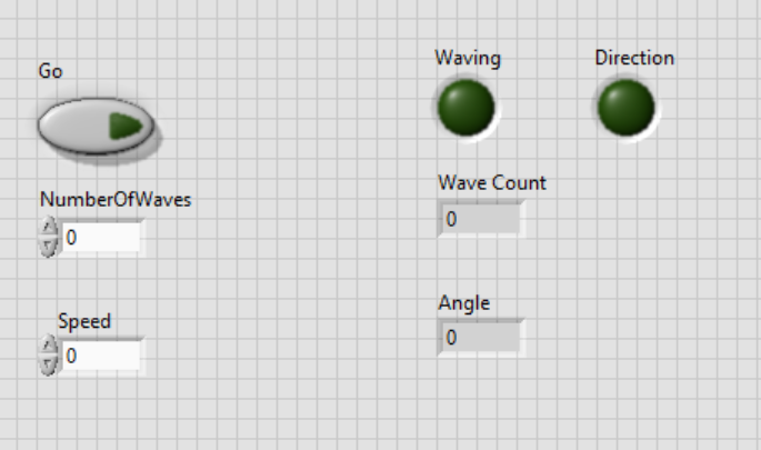
SubVI front panel with Go, NumberOfWaves, Speed, Waving, Direction, Wave Count, and Angle.
These controls and indicators define the automatic waving state.
Wave Servo icon for the automatic waving SubVI.
Edit the SubVI icon so it remains recognizable when placed in the main VI.

Connector pane

Set a pattern with three inputs and one output. Top input to GO, middle to NumberOfWaves, bottom to Speed, output to Angle.

Formula Node starter architecture

Copy this structure into the Formula Node after creating the listed terminals. The TODO comments deliberately leave the automatic-wave behaviour for you to implement and test.

/*
Inputs: GO, NumberOfWaves, Speed
Outputs: Angle, Direction, WaveCount, Waving
*/

// Start from the previous iteration's state.
Angle = AngleLast;
Direction = DirectionLast;
WaveCount = WaveCountLast;
Waving = WavingLast;

// TODO: Start a new sequence when GO is pressed.
// TODO: Increment/Decrement Angle using Speed and Direction.
// TODO: Reverse Direction at your safe angle limits.
// TODO: Update WaveCount after each completed pass.
// TODO: Stop waving when the requested count reaches zero.

Controls

Go, NumberOfWaves, and Speed.

Indicators

Waving, Direction, Wave Count, and Angle.

State inputs

Local variables changed to Read provide AngleLast, DirectionLast, WaveCountLast, and WavingLast.

Logic requirements: initialize state from the previous values; use GO to begin a wave sequence; advance or reverse the angle according to direction; reverse at the safe limits; decrement the wave count at each completed pass; and stop when the requested count reaches zero. Document your own implementation.
Idle->GO pressed->Waving forward->Boundary reached->Waving backward->Count decreases->Idle

Timing and icon

Add Wait with constant 10. Edit the icon, for example Wave Servo. Save the SubVI.

Think it through
  • Why does automatic mode need memory of the previous angle?
  • What do Waving, Direction, and WaveCount represent?
  • What happens when GO becomes true?
  • What condition causes direction to reverse?
  • What does == mean?
  • What does | mean?
  • Why does the code stop when WaveCount reaches 0?
  • Why are local variables used here?
  • What are the risks of using local variables carelessly?

Checkpoint 7

Insert the automatic-wave SubVI into the main VI

Return to the main VI from the Scale Pulse Width stage. Place the saved SubVI in the Automatic case, remove the temporary pass-through connection, and connect the SubVI output to the Case Structure output.

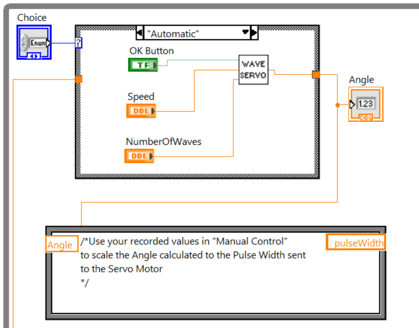
LabVIEW Automatic Case Structure with Choice set to Automatic, an OK button, Speed and NumberOfWaves numeric controls wired to the Wave Servo SubVI, and the Angle output routed to the shared pulse-width Formula Node.
In the Automatic case, wire GO, Speed, and NumberOfWaves into the Wave Servo SubVI. Route its Angle output through the Case Structure tunnel to the shared pulse-width mapping below; use the pulse-width limits you recorded during Manual Control.

Inputs

  • GO to top SubVI input.
  • NumberOfWaves to middle input.
  • Speed to bottom input.

Output

SubVI Angle output connects to the Case Structure output. The shared pulse-width conversion then commands the servo.

Manual mode and Automatic mode produce the same kind of output: an angle command. The shared pulse-width conversion turns either angle source into a servo command.

Think it through
  • Why should both cases output an angle?
  • Why should pulse-width scaling remain outside the Case Structure?
  • What would happen if Automatic output pulse width instead of angle?
  • What does GO trigger?
  • What does Speed change?
  • What does NumberOfWaves change?
  • How will you test that the number of waves is correct?
  • How can you safely stop automatic motion?

For each Setting cell, enter the values you actually used (for example mode, speed, or number of waves), then record your observation and decision for that same test.

TestSettingExpected observationActual observationDecision
Manual modePotentiometer changes command angle
Automatic modeServo waves using GO, Speed, NumberOfWaves
Stop buttonLoop ends and close functions run
If Manual mode works but Automatic mode does not
Keep the known-good wiring and scaling unchanged. Check the Choice selector, SubVI connector pane, Automatic-case output tunnel, and local-variable read direction one at a time, then repeat the same controlled test.

Reflect

Deliverables and assessment

Submit

  1. Completed servo and potentiometer circuit.
  2. Manual-control front panel and block diagram evidence.
  3. Evidence that A0 is read and Digital Pin 7 commands the servo.
  4. Voltage-to-angle and angle-to-pulse-width calculations.
  5. Formula Node explanations.
  6. Completed automatic-wave SubVI with front panel, block diagram, icon, and connector pane.
  7. Final main VI with SubVI in Automatic case.
  8. Manual and automatic mode test evidence.
  9. Explanation of each if statement, ==, |, and local variables.
  10. Three applications of servomotors.
  11. Student names and numbers as required.
  12. Report formatted according to 3CC3 Lab Policies and Report Writing.pdf.

Learning Outcomes Achieved

  • Acquire potentiometer voltage through Arduino A0 with LabVIEW LINX.
  • Scale voltage to commanded angle and angle to a safe servo pulse width on D7.
  • Build Manual and Automatic HMI paths and integrate reusable automatic-wave SubVI logic.
  • Verify controlled motion, normal shutdown, and task-specific fault recovery using evidence.

Reflection questions

Glossary

Servo motor
A motor assembly that moves to a commanded position using an internal control circuit.
Servo horn
The attachment on the servo shaft that transfers motion to a mechanism.
Servo motor plastic arm attachment
The plastic arm fitted to the servo motor shaft before testing motion.
Potentiometer
A variable resistor used here to create a changing voltage.
Analog input
A microcontroller input that reads a voltage range.
Arduino A0
Analog Pin 0, used for the potentiometer voltage.
Digital Pin 7
The Arduino pin used for the servo control signal.
PWM
Pulse-width modulation or timed pulse signaling used by many servo interfaces.
Pulse width
The duration of the servo command pulse, measured in microseconds.
Microsecond
One millionth of a second.
Commanded angle
The angle value calculated by software.
Actual angle
The physical shaft position, which may differ slightly from the command.
LabVIEW
A graphical programming environment.
VI
Virtual Instrument, a LabVIEW program.
SubVI
A reusable LabVIEW program used inside another VI.
Front Panel
The user-facing LabVIEW controls and indicators.
Block Diagram
The graphical LabVIEW program logic.
HMI
Human-machine interface.
LINX
LabVIEW toolkit for communicating with Arduino.
Servo Open
LINX function that prepares a servo channel.
Set Pulse Width
LINX function that writes the servo pulse command.
Servo Close
LINX function that closes the servo channel.
Analog Read
LINX function that reads voltage from an analog channel.
While Loop
A repeated LabVIEW structure.
Stop button
The normal way to stop the VI loop.
Abort button
An emergency interruption, not normal shutdown.
Case Structure
LabVIEW structure that selects code based on Choice.
Manual mode
Mode where potentiometer voltage generates the angle command.
Automatic mode
Mode where the SubVI generates the angle command over time.
Formula Node
LabVIEW node for compact formula-based calculations. Consult the current NI documentation for supported syntax.
Local variable
A LabVIEW object used here to read previous state values.
GO button
Button that starts automatic waving.
Speed
User control for how quickly the angle changes.
NumberOfWaves
User control for requested waving repetitions.
Direction
Boolean state that selects increasing or decreasing angle.
Waving
Boolean state indicating automatic motion is active.
Wave Count
Remaining automatic wave count.
== operator
Equality comparison.
| operator
Logical OR in the Formula Node condition.
LRV
Lower reference value for pulse-width mapping.
URV
Upper reference value for pulse-width mapping.
Saturation
A limit condition where a command or actuator cannot increase further.
Jitter
Small unwanted servo movement or vibration.
IoT motion-control node
A local sensing and motion layer that could later connect to cloud commands or logging.