Prepare

Scenario and objectives

You are building a local motion-control node that receives commands from a LabVIEW HMI, sends those commands over serial to Arduino firmware, and uses a motor driver plus external power supply to move a stepper motor in controlled increments.

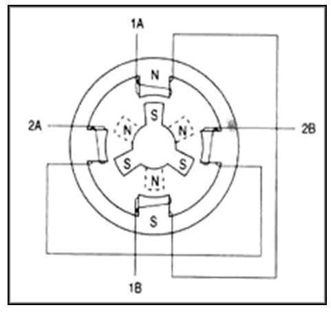
Stepper motor model with windings and a permanent-magnet rotor.
Stepper motor model: energized windings act on the permanent-magnet rotor.
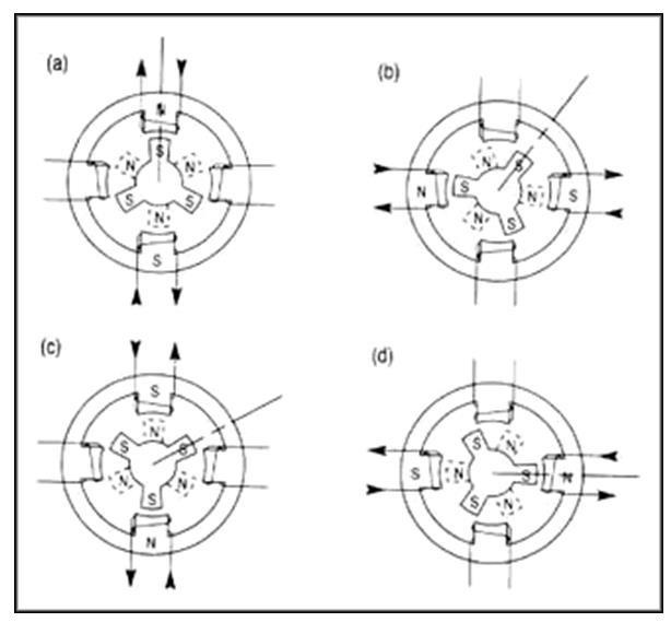
Four winding states that produce stepper motor motion.
Sequential winding states produce controlled, incremental shaft steps.

Learning goals

  • Build and drive a stepper motor with Arduino and LabVIEW.
  • Compile and upload Arduino firmware.
  • Send and parse serial data between LabVIEW and Arduino.
  • Explain the motor driver and external power supply.
WARNING: the stepper motor may heat up during operation. This can be normal, but use caution before touching the motor after it has been energized.

Materials Checklist

Confirm the required materials

Gather the following software, hardware, and course resources before beginning the lab.

Predict

Pre-lab reasoning

Drag the command path into order, or use the numbered selects if you prefer keyboard entry.

Choose an order for every event.

Predict calculations and concepts

PromptGivenYour answerCheck
Steps for 1 revolutionSTEPS_PER_REV = 2048
Steps for 1.5 revolutions clockwise2048 * 1.5 * 1
Steps for 0.5 revolutions counter-clockwise2048 * 0.5 * -1

Checkpoint 1

Prepare the external power system

Use a screwdriver to adjust the power adaptor output to 9 V. Mount the breadboard power supply board correctly and use its regulated 5 V output to power the motor driver circuit.

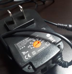
External power adapter with an adjustable voltage selector.
Set the external adapter to 9 V before connecting it to the breadboard power board.
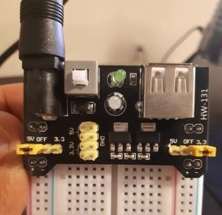
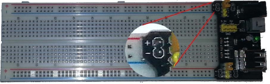
Breadboard power board with yellow jumper positions shown.
Confirm the breadboard power-board orientation and jumper positions.
Breadboard power board installed on a breadboard.
Align positive pins with the red rail and negative pins with the blue rail.
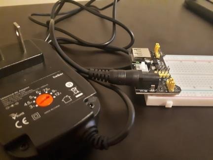
External power adapter connected to the breadboard power board.
Connect the adapter barrel jack to the breadboard power board before motor testing.
STOP - verify polarity before powering. Reversing the breadboard power supply board can reverse project power and damage hardware.

Checkpoint 2

Build the stepper motor driver circuit

Build the circuit using the stepper motor, stepper motor driver, external power supply, breadboard power supply board, Arduino Mega, and jumper wires.

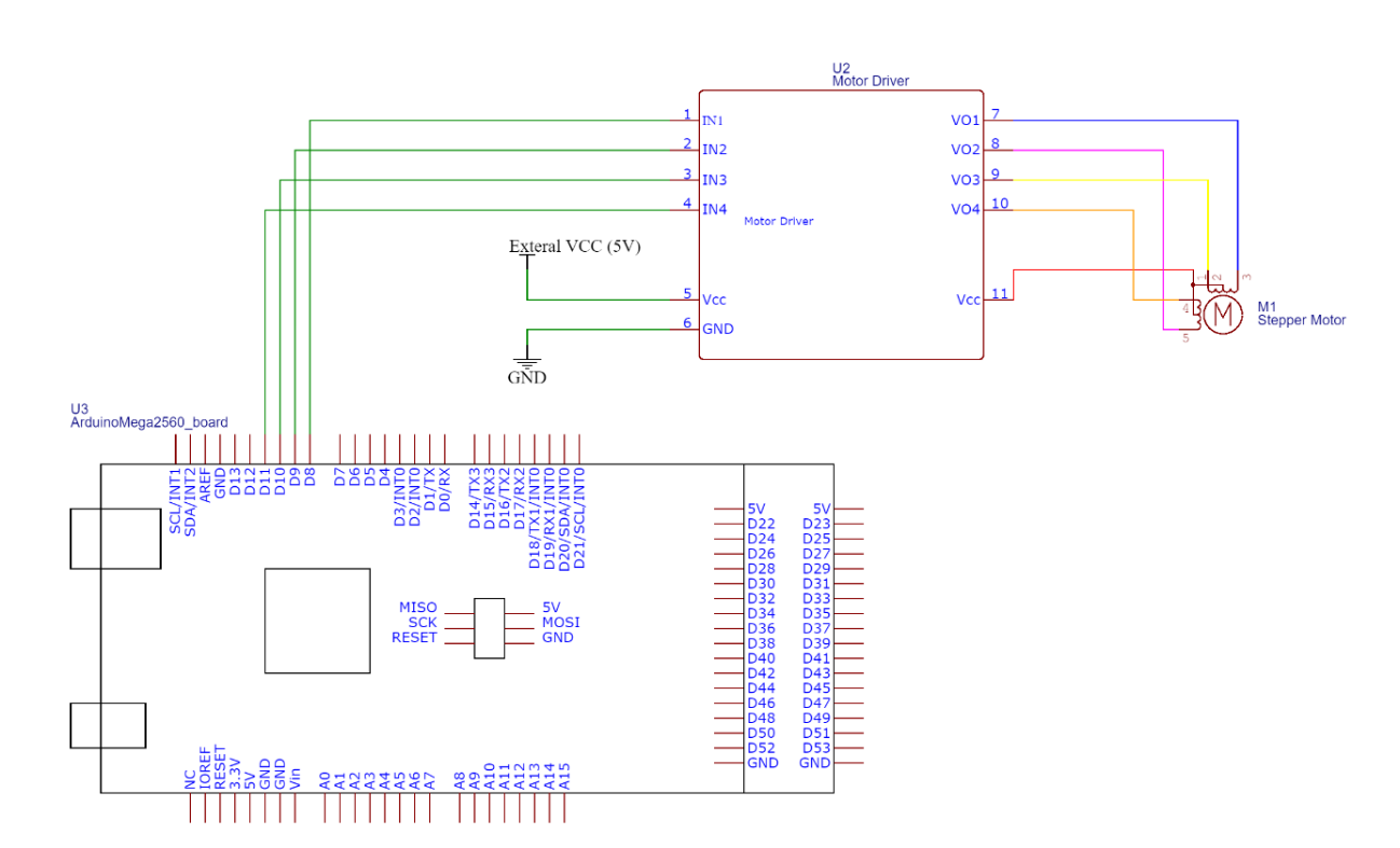
Schematic showing Arduino Mega pins 8 through 11 connected to the stepper driver and external supply.
Connect Arduino pins 8–11 to driver inputs IN1–IN4. The driver receives motor power from the external 5 V rail.
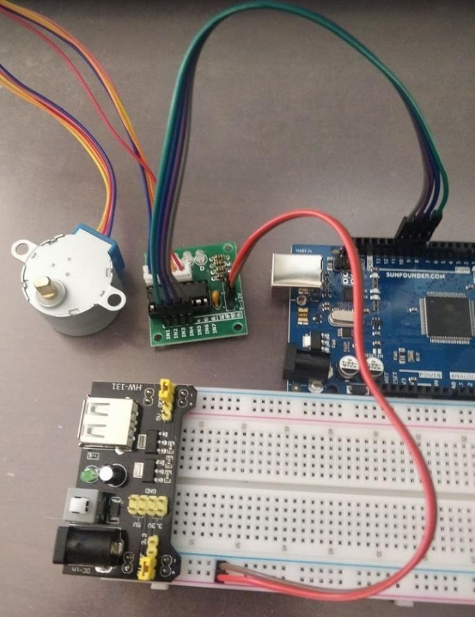
Completed stepper motor, driver, power board, breadboard, and Arduino wiring.
Verify the driver wiring, motor connector, supply rails, and Arduino ground.
Arduino pinDriver pinCheckedNotes
Digital 8IN1
Digital 9IN2
Digital 10IN3
Digital 11IN4

If power or motion is abnormal: switch off the external supply before touching wiring. Recheck 9 V adaptor selection, power-board polarity, regulated rails, common ground, and the D8-D11 to IN1-IN4 mapping before powering again.

Checkpoint 3

Compile and upload the Arduino firmware

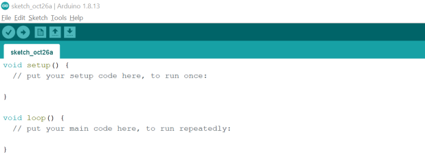
Arduino IDE with stepper motor firmware.
Create a new sketch, paste the provided firmware, verify it, and upload it to the Arduino Mega.

The firmware uses the standard Arduino Stepper.h library, initializes serial communication at 9600 baud, reads a command string until newline, parses comma-separated values, and commands the stepper motor.

#include <Stepper.h>
String command;
String desSpeed;
String desRevs;
String desDirection;

int desSteps = 0;
int firstIndex = 0;
int secondIndex = 0;

const int STEPS_PER_REV = 2048;
Stepper myStepper = Stepper(STEPS_PER_REV, 8, 10, 9, 11);

void setup() {
  Serial.begin(9600);
}

void loop() {
  command = "";
  if (Serial.available() > 0) {
    command = Serial.readStringUntil('\n');
    firstIndex = command.indexOf(',');
    secondIndex = command.indexOf(',', firstIndex + 1);
    desSpeed = command.substring(0, firstIndex);
    desRevs = command.substring(firstIndex + 1, secondIndex);
    desDirection = command.substring(secondIndex + 1);
    desSteps = desRevs.toFloat() * STEPS_PER_REV * desDirection.toInt();
    myStepper.setSpeed(desSpeed.toInt());
    myStepper.step(desSteps);
  }
}

Required actions

  1. Open Arduino IDE and create a new sketch.
  2. Paste the provided code.
  3. Select Tools - Board - Arduino Mega.
  4. Select the correct Tools - Port.
  5. Click Verify and resolve compile errors.
  6. Click Upload to load firmware.

Think it through

  • Why does the sketch include Stepper.h?
  • What runs once inside setup()?
  • What repeats inside loop()?
  • Why does the program look for commas?
  • Why does direction multiply the step count by 1 or -1?

Checkpoint 4

Test command parsing with Arduino Serial Monitor

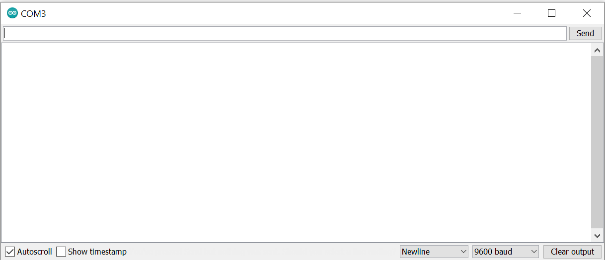
Arduino Serial Monitor for sending stepper motor commands.
Set the baud rate to 9600, enter a command such as 10,1.5,1, and send it to the Arduino.

Use the syntax RPM,Number Revolutions,Direction. For example, 10,1.5,1 requests 10 RPM, 1.5 revolutions, and clockwise direction.

Close the Serial Monitor before running the LabVIEW VI. By default, only one client can use the same serial port at one time.
Command sentExpected motionActual observationMotor heat or lock-up?
If a Serial Monitor command does not produce safe motion
Stop sending commands and switch off motor power if the motor stalls, locks, or becomes hot. Verify 9600 baud, two comma delimiters, the newline setting, direction as 1 or -1, and a conservative RPM before changing one item and retesting.

Checkpoint 5

Build the LabVIEW serial-command HMI

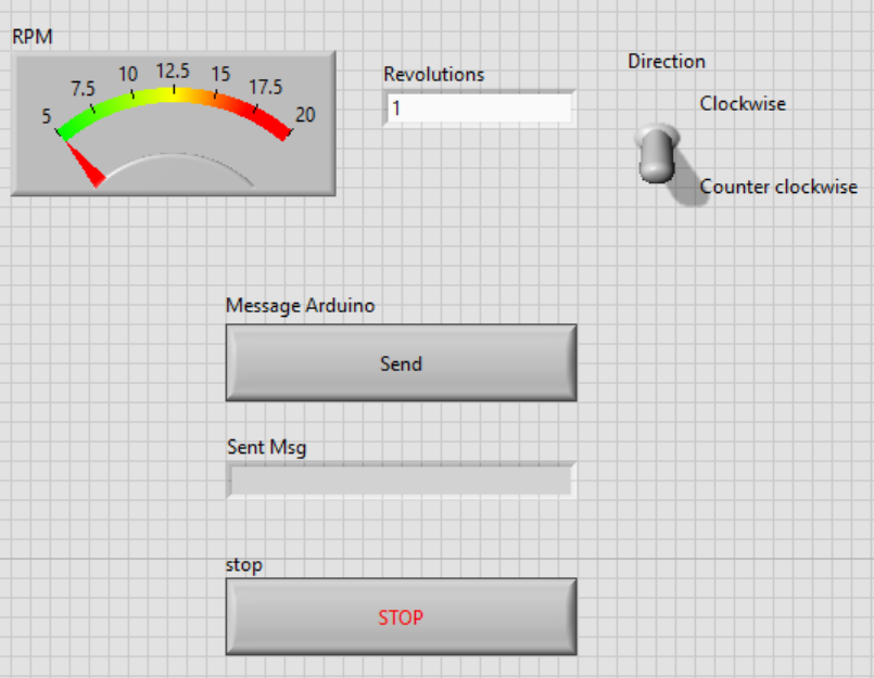
LabVIEW front panel with RPM meter, Revolutions control, Direction toggle, Message Arduino button, sent-message indicator, and Stop button.
The user selects RPM, revolutions, and direction, then sends the command to Arduino.

Front-panel elements

  • OK Button named Message Arduino.
  • Stop button.
  • String control named Revolutions.
  • Vertical toggle named Direction with Clockwise and Counter clockwise labels.
  • RPM meter with scale 5 to 20.
  • Sent Msg indicator for the exact command string.

Reasoning prompts

  • Why should students see the exact string sent to Arduino?
  • Why is direction represented as 1 or -1?
  • Why does RPM have a practical range?
  • What might happen if RPM is too low or too high?

Checkpoint 6

Use LabVIEW VISA Serial to write commands

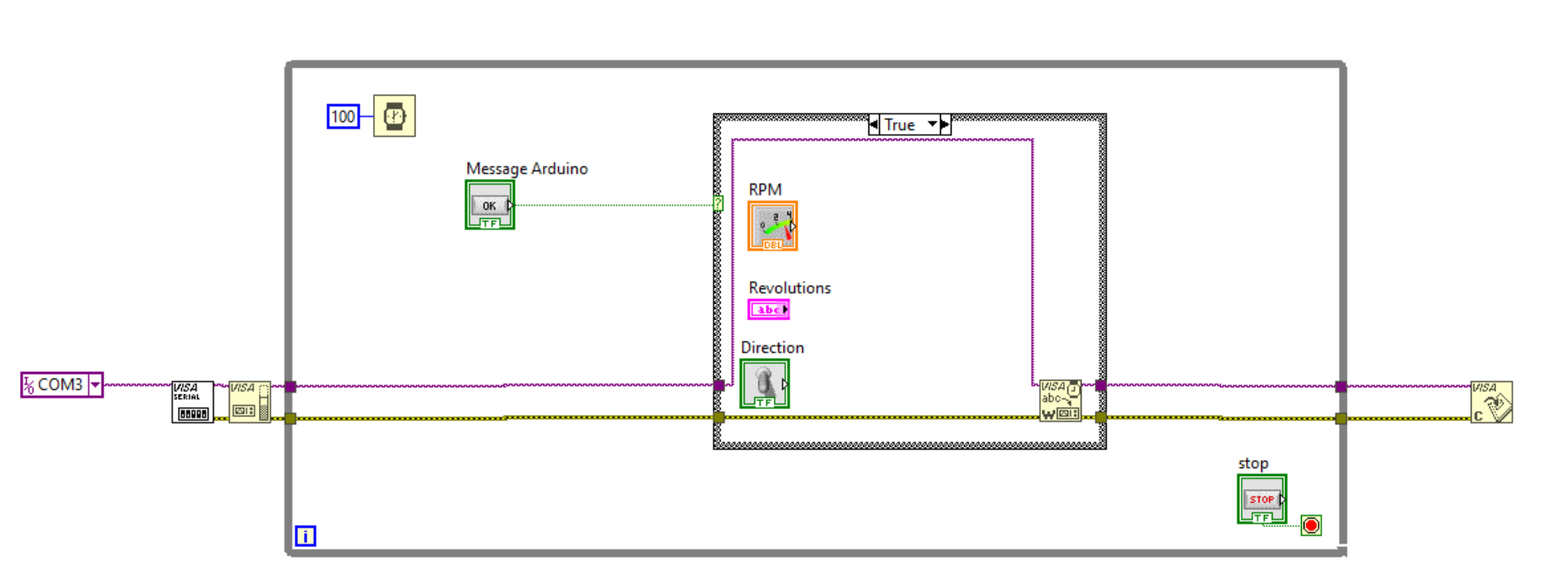
LabVIEW block diagram with serial configuration, buffer, write, close, while loop, wait, and case structure.
Configure the serial port, use a loop and Case Structure, and close VISA after the loop.
Complete LabVIEW block diagram with string concatenation, number conversion, direction selection, sent-message indicator, VISA Write, and close functions.
Concatenate RPM, a comma, revolutions, a comma, and direction into the string written to Arduino.
A. Serial functions

Add Configure Port, Set Buffer Size, Write, and Close from Data Communication - Protocols - Serial. Set VISA Resource Name to the Arduino serial port.

B. Case Structure

Use the Message Arduino button to decide whether to build and send a command string. In the false case, carry wires through.

C. Concatenate Strings

Use five inputs: RPM string, comma, Revolutions, comma, Direction string.

D. Convert RPM

Change the RPM meter from Indicator to Control and wire it through Number to Decimal String.

E. Select direction

Use Select to output string constant 1 for clockwise and -1 for counter-clockwise.

F. Test

Close Arduino Serial Monitor, run the VI, send commands, and observe motor motion.

RPMRevolutionsDirectionExpected sent stringActual sent stringObserved motion
If Serial Monitor works but LabVIEW VISA does not
Close Serial Monitor, verify the VISA Resource Name, confirm the command contains both commas and the required line ending, and check that VISA Write is in the True case. Keep the proven firmware and hardware unchanged while testing one LabVIEW correction at a time.

Extend

Replace revolutions with an angle command

Replace the Revolutions control with an Angle control. Instead of entering 0.5, 1, or 2 revolutions, the user enters 180, 360, or 720 degrees.

Angle commandEquivalent revolutionsExpected steps at 2048 steps/revHow you modified LabVIEW
180 degrees0.51024
360 degrees12048
720 degrees24096
Convert angle to revloutions in LabVIEW before concatenating the serial string.

Reflect

Deliverables and assessment

Submit

  1. Completed stepper motor, driver, power supply, and Arduino circuit.
  2. Arduino IDE sketch with provided firmware uploaded.
  3. Serial Monitor tests using several command strings.
  4. LabVIEW front panel screenshot/export.
  5. LabVIEW block diagram screenshot/export.
  6. Evidence of VISA serial command sent to Arduino.
  7. Explanation of Arduino code and parsing logic.
  8. Extension showing revolutions replaced by angle control.
  9. Answers to the reflection questions.

Learning Outcomes Achieved

  • Power a stepper motor safely through its driver using an external supply and common ground.
  • Upload Arduino firmware and verify comma-delimited motion commands through Serial Monitor.
  • Build a LabVIEW HMI that formats and sends motor commands with VISA Serial.
  • Convert angle requests into motion commands and evaluate speed, direction, holding, and recovery evidence.

Reflection questions

Glossary

Stepper motor
A motor that moves in discrete angular increments called steps.
Holding torque
Torque available when the shaft is not rotating but energized coils resist movement.
Motor driver
Interface circuit that supplies motor current and switches coils based on Arduino control signals.
External power supply
Separate power source used because the motor needs more current than Arduino should supply.
Breadboard power supply board
Regulated board that provides the 5 V rail used by the motor driver in this lab.
Common ground
Shared 0 V reference between Arduino and motor driver circuit.
Stepper.h
Arduino library used to command stepper motor speed and steps.
STEPS_PER_REV
Number of motor steps used in the sketch for one full revolution: 2048.
Serial Monitor
Arduino IDE tool used to send typed serial commands to Arduino.
VISA Serial
LabVIEW communication functions used to configure, write to, and close a serial port.
Delimiter
A character such as a comma used to separate fields in a command string.
RPM
Revolutions per minute, used as the stepper speed command.
Direction
Command field where 1 indicates clockwise and -1 indicates counter-clockwise.
Firmware
Program uploaded to Arduino to parse commands and actuate the motor.
Micro-stepping
Finer step control achieved by partially energizing the windings; it is included here for optional exploration.