Course Project:Three-Level Elevator & 7-Segment Display
Design, integrate, and demonstrate a controller for the miniature elevator using digital ICs, an FPGA, or a justified hybrid architecture.
Open-ended engineering designFour lab sessions
Specification
Define a testable three-floor elevator
Objective
Use digital logic to command a miniature elevator between floors 1, 2, and 3 and show its current floor on a seven-segment display.
Minimum required behavior
Three external pushbuttons request floors 1, 2, and 3.
Three reed switches detect the three floor positions.
The controller commands upward motion, downward motion, and a safe stop through the motor driver.
The carriage stops at the requested floor.
The seven-segment display shows 1, 2, or 3 for the current floor.
Implementation freedom
Primarily digital logic ICs
Primarily FPGA
A justified hybrid of both
You determine the control structure, request handling, signal polarity, pin allocation, and subsystem interfaces.
Required and optional are different.
The three pushbuttons, three reed switches, motor control, three floors, and seven-segment floor display are minimum requirements. Three floor LEDs are optional. Other optional features include flashing the display while moving; additional buttons, LEDs, a buzzer etc., but are not base completion gates.
⚠ INSTRUCTOR PLACEHOLDER — REMOVE OR RESOLVE BEFORE STUDENT RELEASE Confirm the supplied 24 V motor running and stall current, the approved motor supply/current-limit setting, the prewired connector mapping, and that the course SN754410 setup remains within electrical and thermal operating limits.
Interface plan
Plan signals and power before construction
Buttons and reed sensors
Control logic
Motor-driver control inputs
Motor-driver outputs
Motor and elevator
Electrical boundary
Never connect the motor or its supply to an FPGA GPIO or ordinary logic output. Power OFF before rewiring. Keep hands and loose wires clear of moving parts, and remove motor power immediately if motion is unexpected.
Instructor-supplied elevator interface board
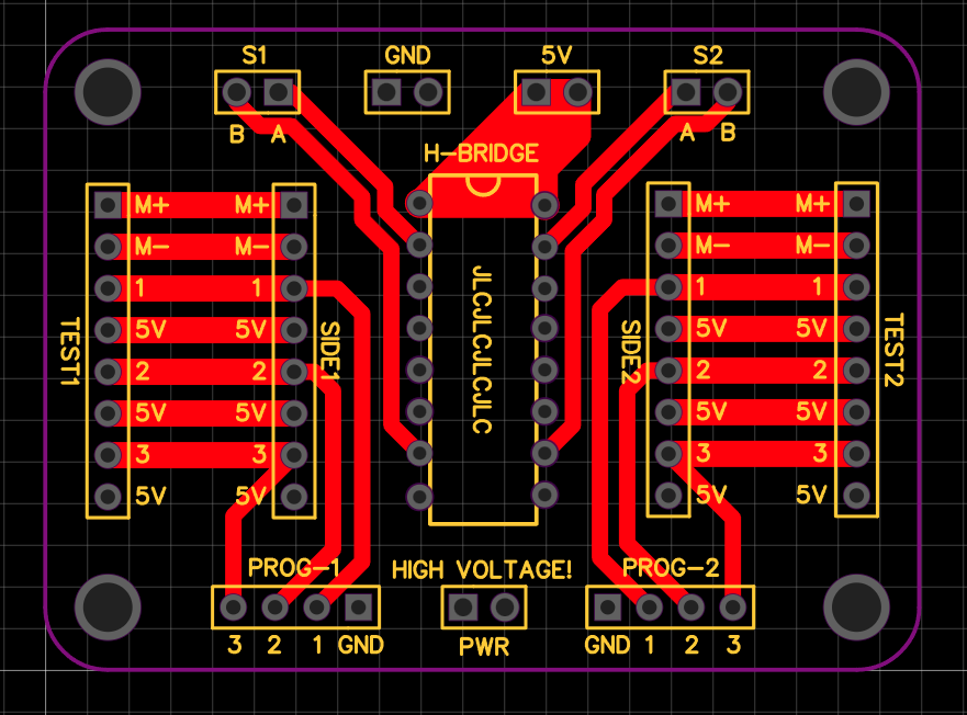
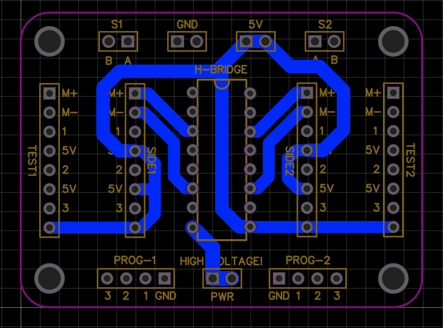
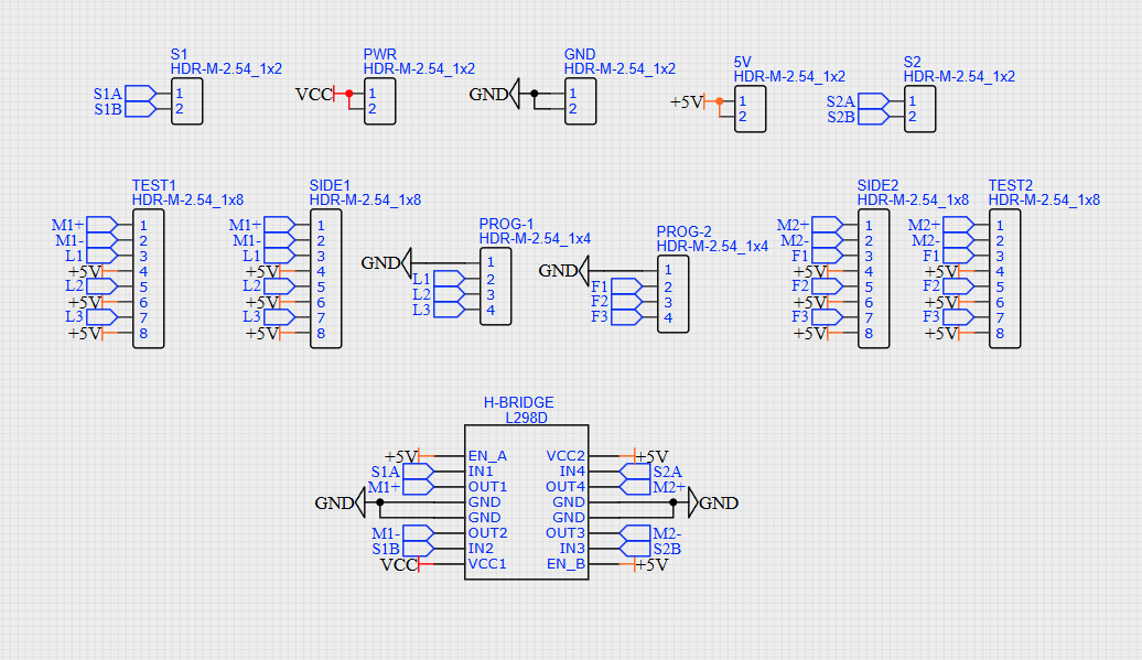
Use these three views together to identify the board connectors and trace routing. The schematic is the functional reference; the red and blue images are the top- and bottom-copper PCB views. They are not three different wiring options.
Interface schematicUse the net names to relate the sensor, motor, floor-signal, programming, power, and driver connections.PCB top-copper viewRed traces show the routed connections on the top layer. Connector labels are component-side references.PCB bottom-copper viewBlue traces show the bottom layer. A bottom-layer view is not a second component-side pinout.
⚠ INSTRUCTOR PLACEHOLDER — REMOVE OR RESOLVE BEFORE STUDENT RELEASE The new interface schematic labels the driver footprint L298D and shows rails/net names that do not establish the final motor-supply voltage. The original project material specifies SN754410/SN754410NE and a 24 V motor. Confirm the actual fitted driver, board revision, connector pinout, motor-supply input, logic-supply input, grounding, and current/thermal suitability before students energize this board. Do not treat L298D and SN754410 as interchangeable from package position alone.
Original SN754410NE reference (top-view PDIP)
Channel pair 1–2 used as a reversible motor driver
Pin
Function
Design meaning
1
1,2EN
Active-HIGH enable for outputs 1Y and 2Y
2 / 7
1A / 2A
Logic direction commands
3 / 6
1Y / 2Y
Motor terminals
4, 5, 12, 13
Ground / heat-sink pins
Connect according to the verified power plan
8
VCC2
Motor/output supply; 4.5–36 V device range
16
VCC1
Logic supply; 4.5–5.5 V recommended
The device provides TTL-compatible inputs, separate logic and output supplies, internal clamp diodes for inductive loads, and thermal shutdown. Its advertised driver capability is 1 A, but current, voltage drop, package dissipation, ambient temperature, and motor stall current must all be checked. Absolute maximum ratings are not design targets.
Course diagram note: the supplied classroom wiring diagram illustrates a 9 V motor topology. Use it only as a topology reference; it does not establish the final 24 V supply arrangement or prove current compatibility.
⚠ INSTRUCTOR PLACEHOLDER — REMOVE OR RESOLVE BEFORE STUDENT RELEASE Physically confirm the actual reed-switch active behavior, pushbutton configuration, connector pinout, and which motor polarity produces up/down before authorizing motor-power testing.
Verification
Demonstrate the complete elevator
Submission
Prepare the project record and official submissions
Three separate actions
Use this page to save planning and select files for a local ZIP.
Demonstrate the working elevator to the instructor (about 10 minutes per group).
Submit the required files through Avenue to Learn. Downloading the local ZIP does not submit anything.
Project Summary: complete the supplied summary template and submit it on Avenue before the demonstration.
Written report: one DOCX or PDF per group covering topic, resources and pin assignments, digital design, decision-block flowchart, final photos, one coloured digital wiring diagram, feature summary, limitations, design selection, and achievements.
Design archive: submit one ZIP of rebuildable design files. FPGA/hybrid paths include the Quartus project and student-authored source; a discrete path includes the complete digital design/schematic files used to build the circuit.
Peer evaluation: each student separately submits a contribution evaluation.
Team details
Selected files are included only in this local ZIP. After reopening the page, reselect every evidence file before exporting.